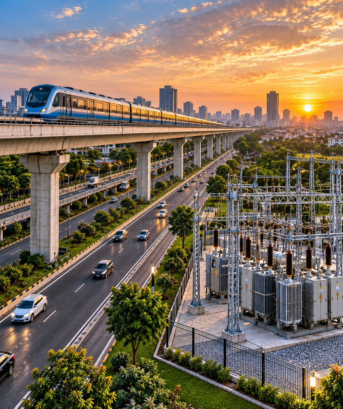
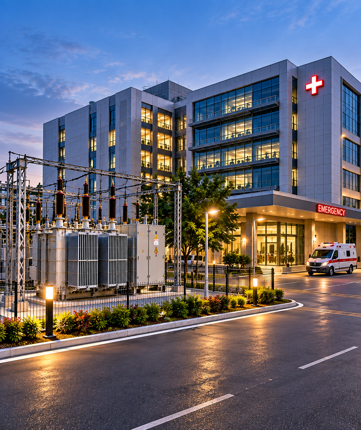
AIS / GIS / VCB / RMU architecture for project-specific duty.
Selected and coordinated around voltage class, fault level, current rating, service continuity, space and operating philosophy.
RELIABLE POWER FROM THE GRID TO YOUR CRITICAL LOADS
Alpha Numeric Innovations delivers coordinated high-tension electrical infrastructure from 11kV through 33kV — integrating utility interface, AIS/GIS switchgear, VCB and RMU systems, transformers, protection, metering, HT cabling, earthing, testing and controlled energization under one design and execution framework.
HT infrastructure performs as a system only when ratings, fault levels, insulation class, protection philosophy, switching sequence, cable interfaces, earthing and downstream transformation are coordinated as one system. Our delivery model treats the 11kV–33kV network as one coordinated architecture from grid interface to the final HT/LT boundary.
A conceptual project sequence that can be adapted for industrial plants, campuses, commercial facilities and infrastructure projects.
HT projects are won or lost at the interfaces. We therefore show the complete scope—not only the switchboard.
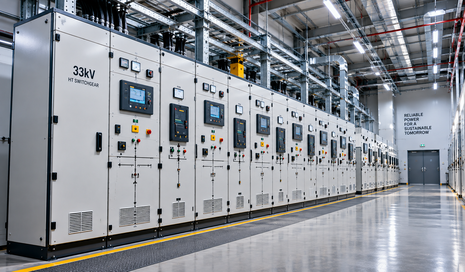
Indoor or outdoor switchgear architecture including AIS/GIS, VCB panels, RMUs, bus sections, incomers, outgoing feeders and couplers.
Protection relay philosophy, CT/PT interfaces, trip circuits, annunciation, interlocks, breaker control and coordination with downstream systems.
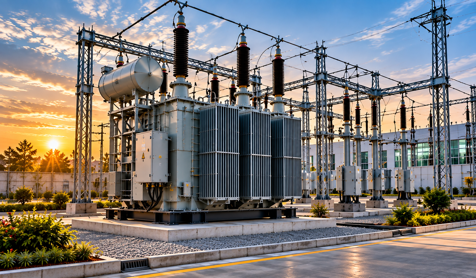
Power/distribution transformers, compact substations, indoor substations, outdoor yards, neutral earthing and associated HT/LT interfaces.
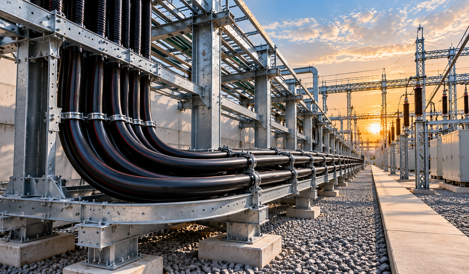
HT cable sizing support, routing, trays/trenches, joints, terminations, glands, sealing, identification and interface coordination.
Substation earth grid, equipment bonding, touch/step considerations, earth pits, neutral earthing and safe isolation provisions.
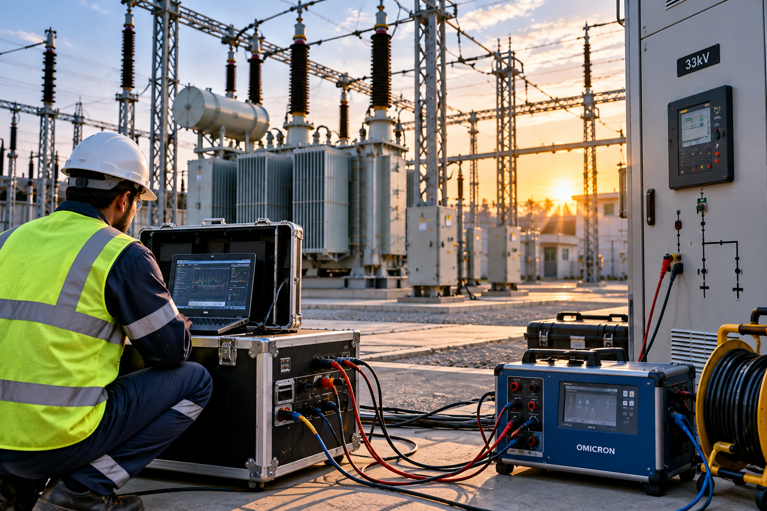
Pre-commissioning checks, relay/functional verification, cable tests, interlock checks and controlled energization with documented handover.
The system is only as strong as its switching, protection, cable interfaces, terminations, clearances and commissioning discipline.
Selected and coordinated around voltage class, fault level, current rating, service continuity, space and operating philosophy.
Project-specific ratings and studies depend on approved inputs, utility requirements and equipment data.
Source, bus, transformer, feeder and redundancy architecture.
Equipment duty alignment with available fault-level information.
Relay logic, breaker trip philosophy and selectivity support.
Equipment and cable interfaces aligned to the applicable voltage class.
Routes, sizes, terminations, joints and installation interfaces.
Grid, bonding, neutral and equipment earthing interfaces.
Electrical/mechanical interlocks and safe switching sequences.
Approved drawings, test sheets, settings and closeout documentation.
Source voltage, sanctioned demand, location, routes, space and interface constraints.
StudySLD, layouts, equipment schedules, protection philosophy and civil/electrical interfaces.
DesignSwitchgear, transformers, protection, metering, cables and accessories to approved specs.
SupplyPanels, yard equipment, cable laying, joints, terminations, earthing and control wiring.
ExecuteInspection, functional checks, relay settings verification and cable/equipment tests as applicable.
VerifySequence-based energization, final checks, test records and operational handover.
Commission
The final testing plan is project and equipment specific. The objective is to verify insulation, wiring, protection, interlocks, earthing, control logic and switching readiness before the system is energized.
The architecture changes with load criticality, redundancy, space, environmental conditions and utility requirements.
Motor loads, furnaces, process continuity, captive/utility interfaces and scalable substations.
Utility incomers, multiple transformers, redundancy and central power infrastructure.
Distributed substations, outdoor networks, long cable routes and critical services.
Redundancy, selective protection, controlled changeover and operational continuity.
Our differentiator is the way the entire HT chain is coordinated—source, switching, protection, transformation, cabling, earthing, site interfaces and commissioning—not just one equipment package.
Share your SLD, sanctioned load, utility voltage, tender scope or site requirements. We can structure the 11kV–33kV package from grid interface through switchgear, transformation, protection and commissioning.
Discuss HT Project